





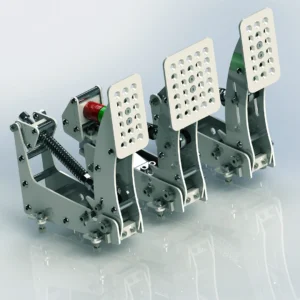
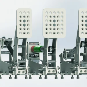
Description


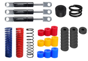
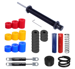
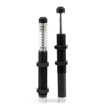
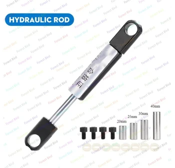
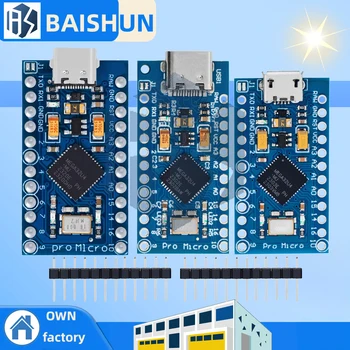
- Quantity: 1
- Option: Micro USB
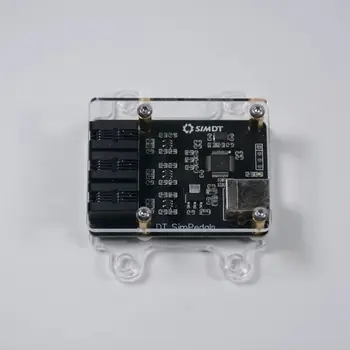
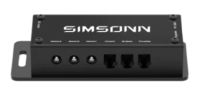
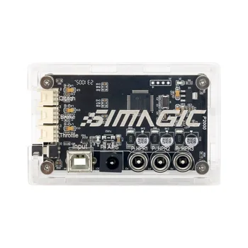
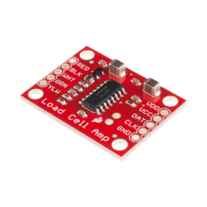
- Note: compatible only with HX711 Loadcell Amplifier








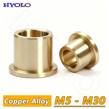
Flanging Self-Lubricating Bearing
- Quantity: 2
- Option: 6x10x12-14×2
- Inner Diameter: Ø6mm
- Outer Diameter: Ø10mm
- Width: min 12mm, max 15mm

Flanging Self-Lubricating Bearing
- Quantity: 2
- Option: 6x10x15-16x2mm
- Inner Diameter: Ø6mm
- Outer Diameter: Ø10mm
- Width: min 12mm, max 15mm











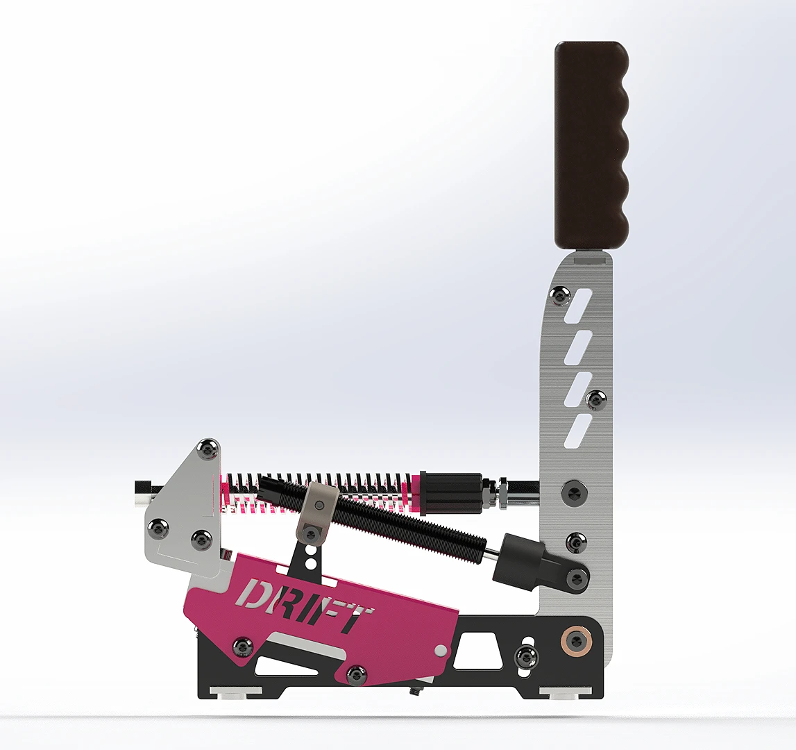
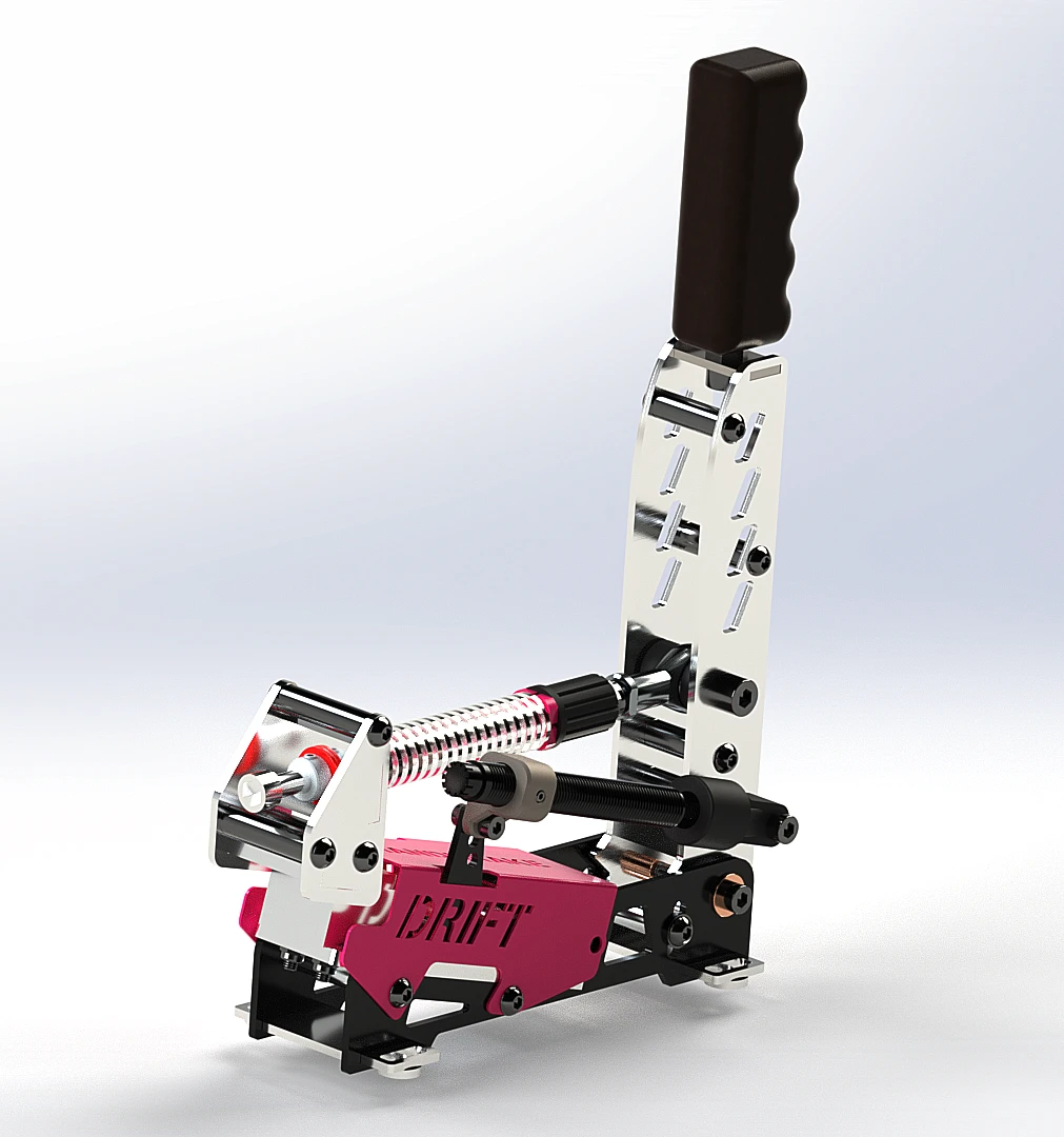
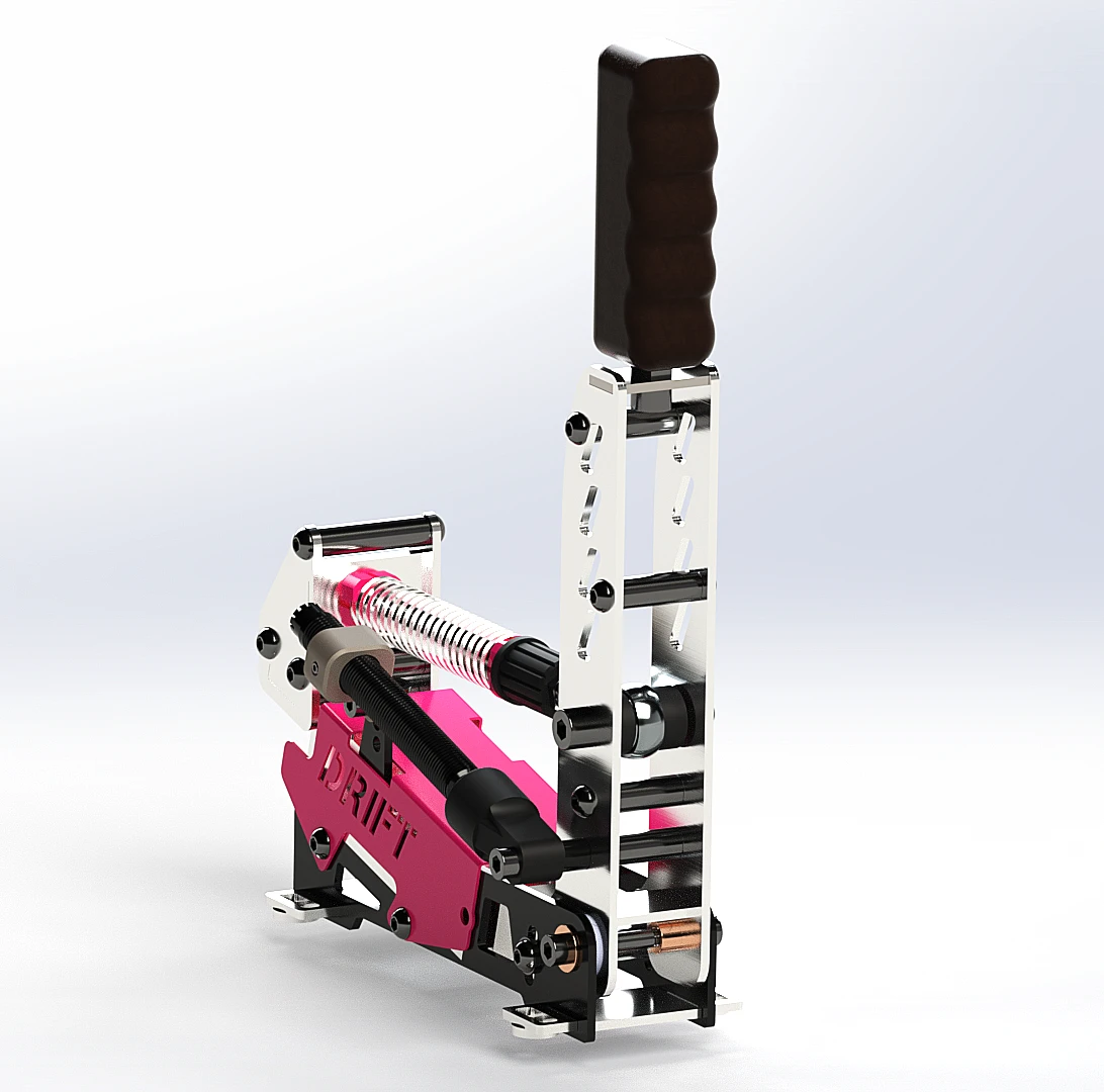
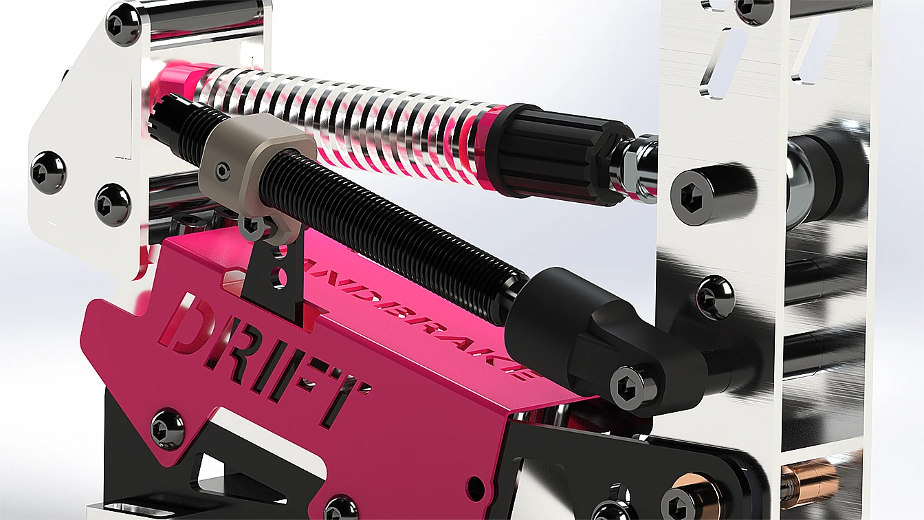
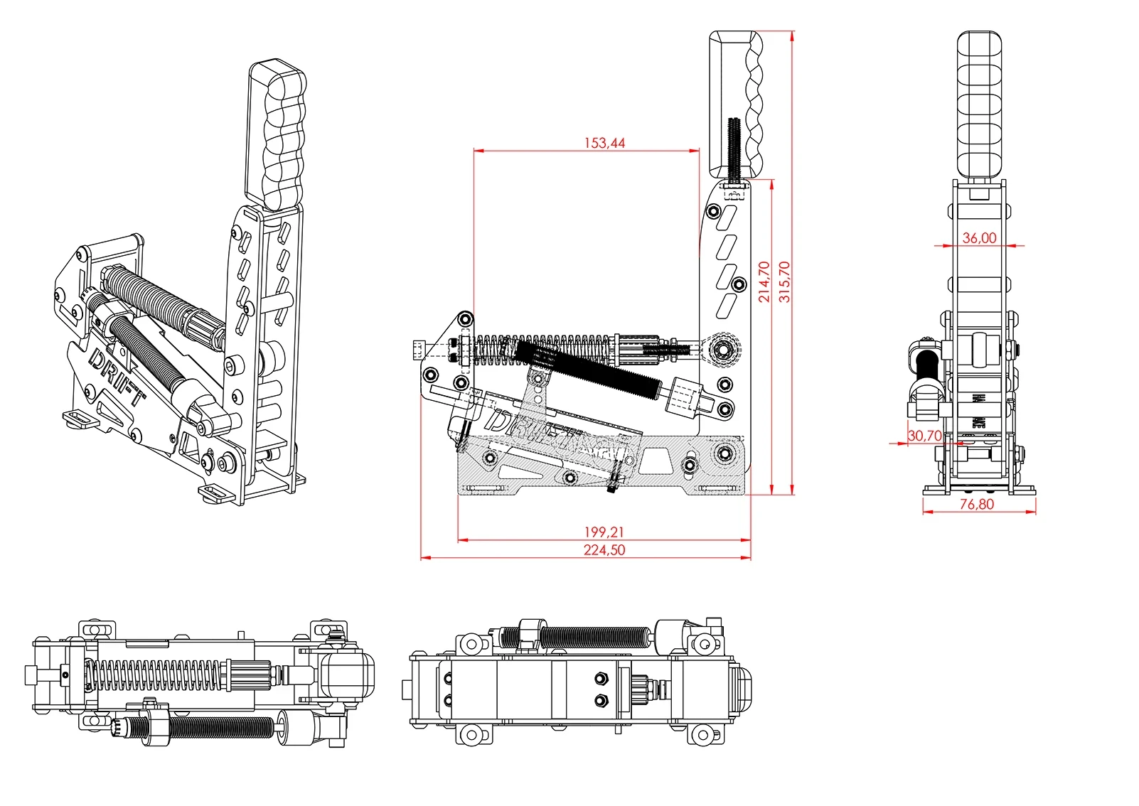
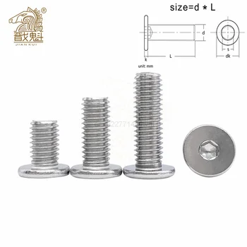
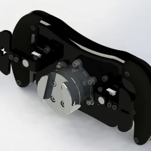
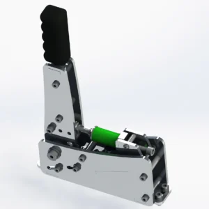
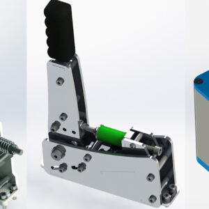
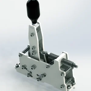
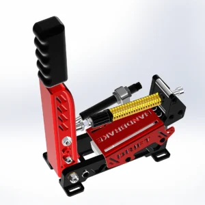
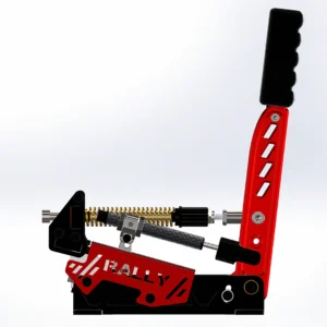
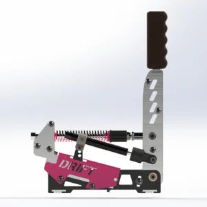
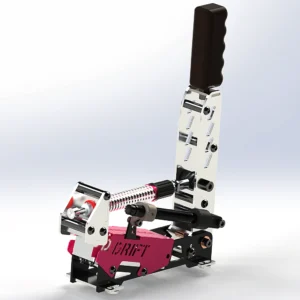
This handbrake assembly is constructed from stainless steel plates of various thicknesses (primarily 3 mm, with some 2 mm and 5 mm).
The plates are connected using M6x40 and M6x30 Threaded Round Spacers.
This is our most asked question! Everything you need is listed in the BOM (Bill of Materials). You can find it in two places:
Directly within the BOM section of the product page.
Inside the comprehensive Readme PDF included with your purchase. It includes exact quantities, dimensions, and even direct sourcing links to save you time.
- You can also find many parts on our DIY Tools page.
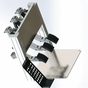
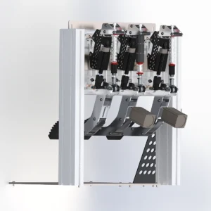
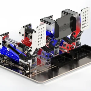
Here is the list of hardware needed to build a pedal; simply multiply the quantities by two or three if you
wish to make two or three pedals. The list does not include the hydraulic cylinder or the bass shaker,
which are optional parts.
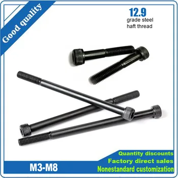
- M6x12 Bolt – Quantity 18
- M8x40 Bolt – Quantity 1
- M8x45 Bolt – Quantity 1
- M8 Lock Nut – Quantity 2
- M8 Nut – Quantity 2
- M6x55 Bolt – Quantity 1
- M6 Lock Nut – Quantity 1
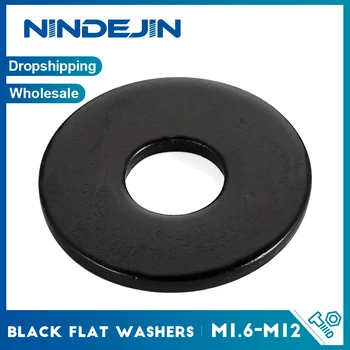
- M6 Washer – Quantity 2
- M6x40 Threaded Round Spacers – Quantity 10 (3D Printed Alternative is available)
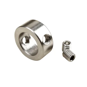
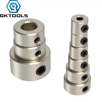
- 8mm Drill Bit Collar – Quantity 1 (3D Printed Alternative is available)
- M8 Female Rodend – Quantity 1 (3D Printed Alternative is available)
- M8x180 Half Thread Bolt – Quantity 1
- Note: M8x170 is also accepted
- M5x40 Bolt – Quantity 2
- M5x35 Bolt – Quantity 2
- Self-Lubricating Bearing – Quantity: 2
No! The Cover (“Fixed Part Cover”) is purely optional. It was designed to give the handbrake set a “Pro-Racing” look. The handbrake are 100% structurally functional without it. You can choose not to install it for a more “industrial/raw” look.
Ease of Assembly: 7/10. If you have basic DIY skills (soldering, using a wrench, and basic 3D printing knowledge), you can build this. The assembly is straightforward thanks to our detailed videos guide and the fact that most parts are “bolt-on.” No complex machining or welding is required.
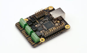
It depends on your electronics. If you use an Arduino with our recommended sketch, you can use Windows Joystick, DIVIEW or FreeJoy for calibration. If you choose a Leo Bodnar or AliExpress Plug & Play board, they are recognized as standard Windows Game Controllers and can be calibrated directly in-game or via Windows settings.
To calibrate your pedal set, feel free to follow our Youtube guide here.
First of all, we invite you to carefully check your soldering, as well as the installation of the Joystick and HX711 libraries.
Issue: I got an error message when compiling my sketch.
- Use another USB cable (a data transfer cable)
- Change the USB port
- Connect the USB board directly to the PC
- Make sure you have chosen the right PORT and the right Board in the Arduino software (“Tools” menu).
Issue: My load cell pressure is reversed
Edit a line of the Arduino sketch, you need to remove or add the – just before scale
Issue: I have a dead zone when pressing my load cell
Slightly adjust the tightness of the four M4 and M5 lock nuts which support the loadcell.
Issue: There is a lack of responsiveness on my load cell, a slight delay.
The HX711 sensor needs a slight modification; a connection needs to be cut and an image reconnected. Here’s an image to help you:
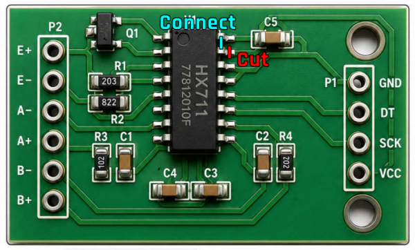
And a video: https://www.youtube.com/watch?v=0cxS-a837bY
A 20kg Load Cell is ideal. Since the handbrake is travel-based, a 20kg sensor offers extreme precision and durability without requiring excessive hand force.
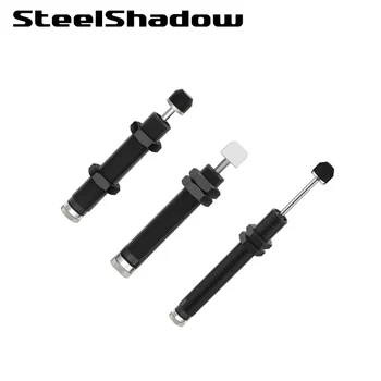
No, the handbrake work perfectly with the included spring or/and elastomer system. The Hydraulic Damper is an optional upgrade for those seeking a more “viscous” and realistic hydraulic feel on the handbrake.
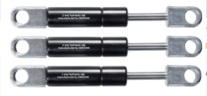
The handbrake is designed to be compatible with two types of dampers:
Standard Gas Struts: Affordable and effective for consistent resistance.
Adjustable Hydraulic Dampers: For those who want to fine-tune the “viscous” damping effect to their exact preference.
To ensure the longevity of your dampers, please follow these three critical rules:
Perfect Alignment: Ensure the actuator rod is perfectly straight during the stroke. It should not deflect left or right when pressure is applied.
Structural Integrity: The “Hydraulic Damper Support” part must be printed with 100% infill to handle the mechanical load without flexing.
Mechanical Stops: This is the most important step. Your pedal’s physical travel must be limited by the “Fixed Part” stop (the M6x40 spacer) before the hydraulic damper reaches its internal end-of-stroke. Never use the gas damper as a mechanical stop. Forcing the pedal against a fully compressed damper will lead to immediate failure.
- For the screws securing the Rodend and which screws onto the M6x40 fitting, we recommend using
a thread-locking compound to prevent them from coming loose due to vibration. This adhesive.
Like most DIY hardware, this set is natively compatible with PC. To use it on a console, you would need a third-party adapter (like a DriveHub) and a compatible interface (like a Leo Bodnar board or Arduino).
Unlike potentiometers, Load Cells have no moving electrical parts that can wear out or get twitchy with dust. They provide a much higher resolution and rely on pressure, which is far more consistent for muscle memory than handbrake distance.
Yes! The pack includes a professional Video assembly tutorial with exploded views, a full Bill of Materials (BOM) with purchase links.
Our design is flexible to fit your budget and technical comfort:
Open Source Path: Use an Arduino Pro Micro + HX711 for each pedal.
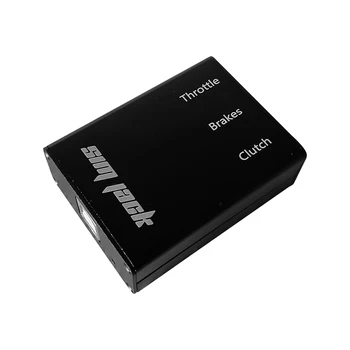
Plug & Play Path: Use a Leo Bodnar board or a specialized AliExpress Sim Racing controller for a “no-coding-required” setup.
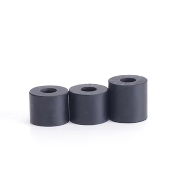
To ensure perfectly silent operation and avoid any clicking sounds when the handbrake returns, place the rubber washer at the very end of the M8x180 bolt, just before the locking collar.
Pro Tip: For the best results, glue the washer directly onto the part named “Load Cell Pressure”. This acts as a silencer, preventing the rod from striking the component directly during rapid pedal release.
To ensure a perfect fit with the internal mechanisms, please follow these specifications when sourcing your hardware:
Hydraulic/Gas Damper:
Maximum Outer Diameter: Ø15mm
Maximum Length: 140 mm
Springs:
Minimum Inner Diameter: Ø8mm (to slide freely over the M8 rods).
Elastomers (Rubbers):
Minimum Inner Diameter: Ø8mm
Maximum Outer Diameter: Ø35mm (to fit within the handbrake housing/washers).
Only the cover plate (decorative) and the brackets for the handbrake rests need to be bent. Rest assured,
these are purely optional parts and are not required for the handbrake unit to function. The bends are
simple (90°).
The thickness is generally 3 mm, though there are some that are 5 mm and 2 mm thick.
The tolerance is 0,2 mm.
The fixed section of the handbrake assembly consists of two parts:
- Fixed Part A – 3mm Thickness – Quantity 1
- Fixed Part B – 3mm Thickness – Quantity 1
Part A is the side plate that supports the hydraulic damper.
Part B is the side plate that does not support a hydraulic damper.
If you do not wish to use a hydraulic damper, you should use two of Part B; if you wish to use hydraulic dampers on both sides, you can use two of Part A for your handbrake.
We recommend using the standard configuration: Part A + Part B.









Reviews
There are no reviews yet