
Glozin
Professional CAD Files
Glozin
24/7 Free Support & Help Section
Glozin
Step-by-Step Tutorials
Glozin
Save Money
Glozin
Beginner-friendly
Glozin
Instant download

Description

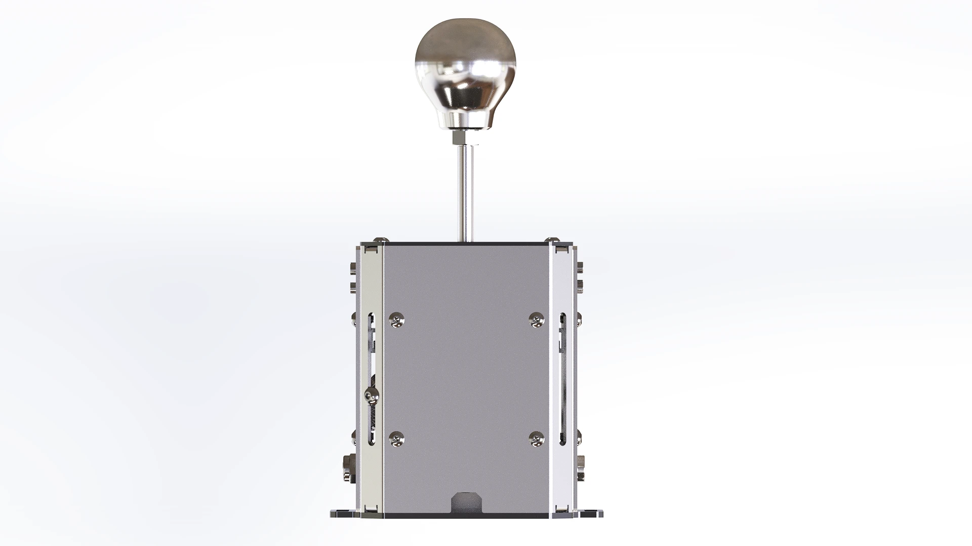
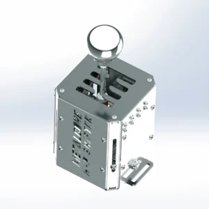
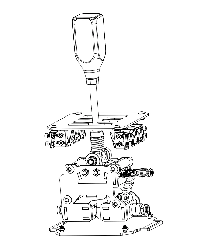
diy metalcore h pattern shifter stainless steel

Feel Every Gear Change.

Authentic Driving Experience

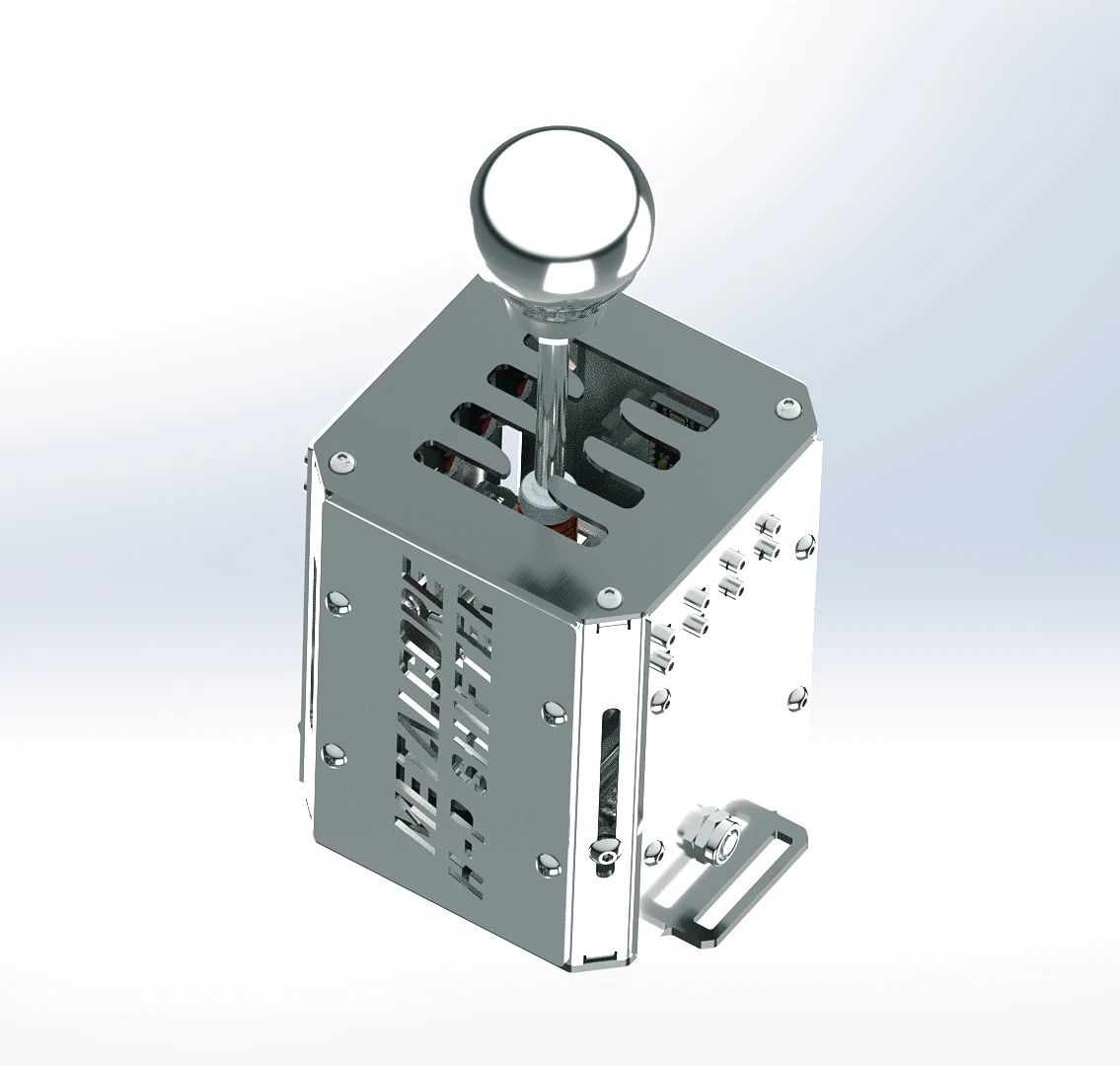
Every component has been engineered to recreate the tactile feedback of a real manual transmission. From the centering force to the gear engagement, the MetalCore H-Pattern Shifter offers a realistic and immersive shifting experience that transforms every lap.

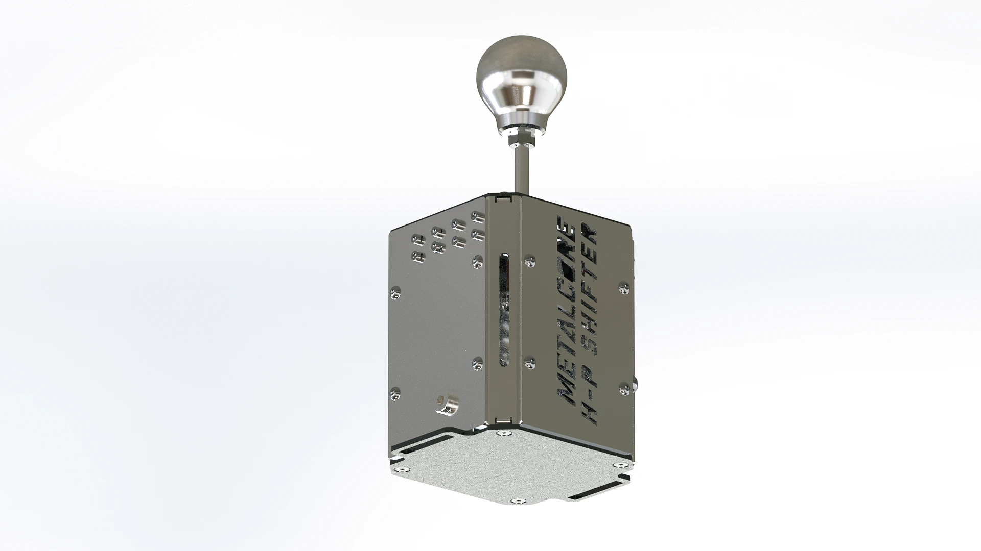
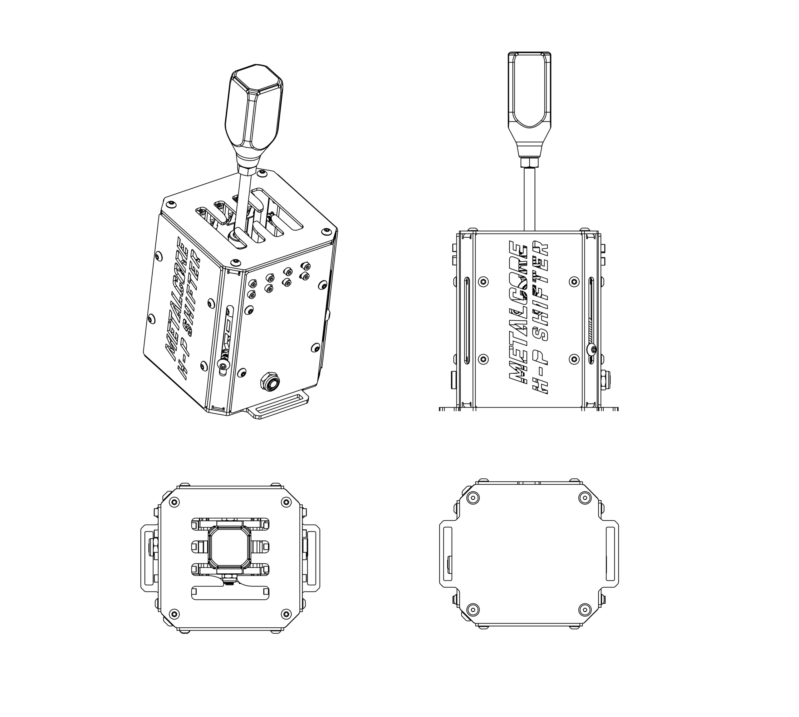
The entire chassis is manufactured from 100% laser-cut stainless steel, resulting in an exceptionally rigid and durable construction.

The mechanism combines:

  • Precision ball bearings
  • Compression spring
  • Extension springs
  • Low-friction moving parts
  • M8 Female Rodend

to provide smooth and accurate gear changes.

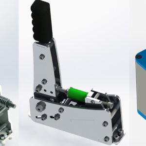
MetalCore H-Pattern Shifter - Sim Racing DIY Project - 09

Fully Adjustable

MetalCore H-S Shifter isn’t just realistic — it’s built around personalization.

Fine-tune the shifter exactly the way you like it:

  • Adjust the shifter throw (short or long travel)
  • Modify the centering spring tension
  • Change the shifting resistance
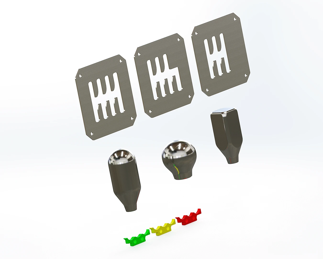
  • Customize the engagement feel with three 5mm Thickness Stainless Steel interchangeable detent profiles (Green, Yellow and Red in the schema)
  • Swap between different gear grid layouts
  • Install your preferred shift knob

Included Gear Plates

Choose the transmission that matches your favorite cars.

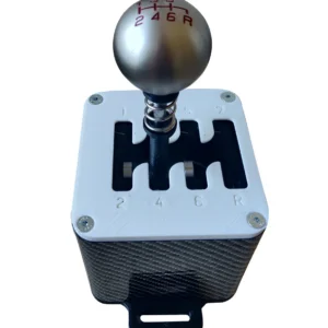
  • 5-Speed H-Pattern
  • 6-Speed H-Pattern
  • 7-Speed H-Pattern

Multiple Shift Knobs Included

Personalize the look and feel of your cockpit with three different shift knob designs, all included with the project files.

Designed for Laser Cutting

MetalCore H-Pattern Shifter has been specifically engineered for efficient manufacturing.

The project requires:

  • Laser-cut stainless steel parts
  • Simple 45° and 90° bends
  • Standard hardware
  • Basic assembly tools

No complex machining is required, making the project accessible while maintaining a premium mechanical result.

ELECTRONICS

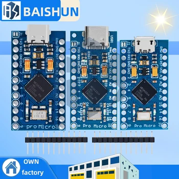
Arduino Pro Micro USB Board

  • Quantity: 1
  • Option: Micro USB
  • Note: compatible only with HX711 Loadcell Amplifier
MicroSwitch

  • Option: Type 2 (16mm Handle Length)

MicroSwitch alternative

  • Option: KW12-B 16mm 5pcs

Alternative USB Board 

  • Option: USB Arcade Encoder Zero Delay

Shielded cable 

  • Quantity: 1
  • Specification: 3 cores 5 meters

SPRINGS

 Lever Spring

  • Length x Diameter x Wire Diameter: 20 x 18 x 1.8
  • Quantity: 1

Alternative Lever Spring

  • Quantity: 1
  • Length: 20x10x20mm
  • Color: Yellow

Side tension spring 1 

  • Length x Diameter x Wire Diameter: 30 x 8 x 1
  • Quantity: 1

Side tension spring 2 

  • Length x Diameter x Wire Diameter: 30 x 8 x 1
  • Quantity: 1

Side tension spring 2 alternative link

  • Length x Diameter x Wire Diameter: 30 x 8 x 1
  • Quantity: 2

Side tension spring 1 alternative link

  • Length x Diameter x Wire Diameter: 30 x 8 x 1
  • Quantity: 2

HARDWARE SCREWS

ALTERNATIVE KNOB

ASSEMBLY AND SOLDERING

It is primarily constructed from 2mm, 3mm and 5mm thickness Stainless Steel laser-cut parts joined using
M6x40 threaded round spacers and screws. Some parts require bending, but these involve only simple 90
or 45-degree bends.

Alternative parts are also available in STEP and STL formats.

You should start by finding a supplier that offers affordable laser cutting and bending services.
Alternatively, JLCCNC’s “Sheet Metal Fabrication Services” is a great option in terms of pricing and
production speed.

There are also several 3D-printable parts available that could help you cut costs—such as M6x40
connectors. You can find all of them in STL format.

For files intended for Stainless Steel laser cutting, the tolerance is 0.2 mm.

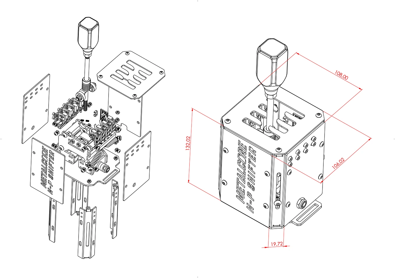
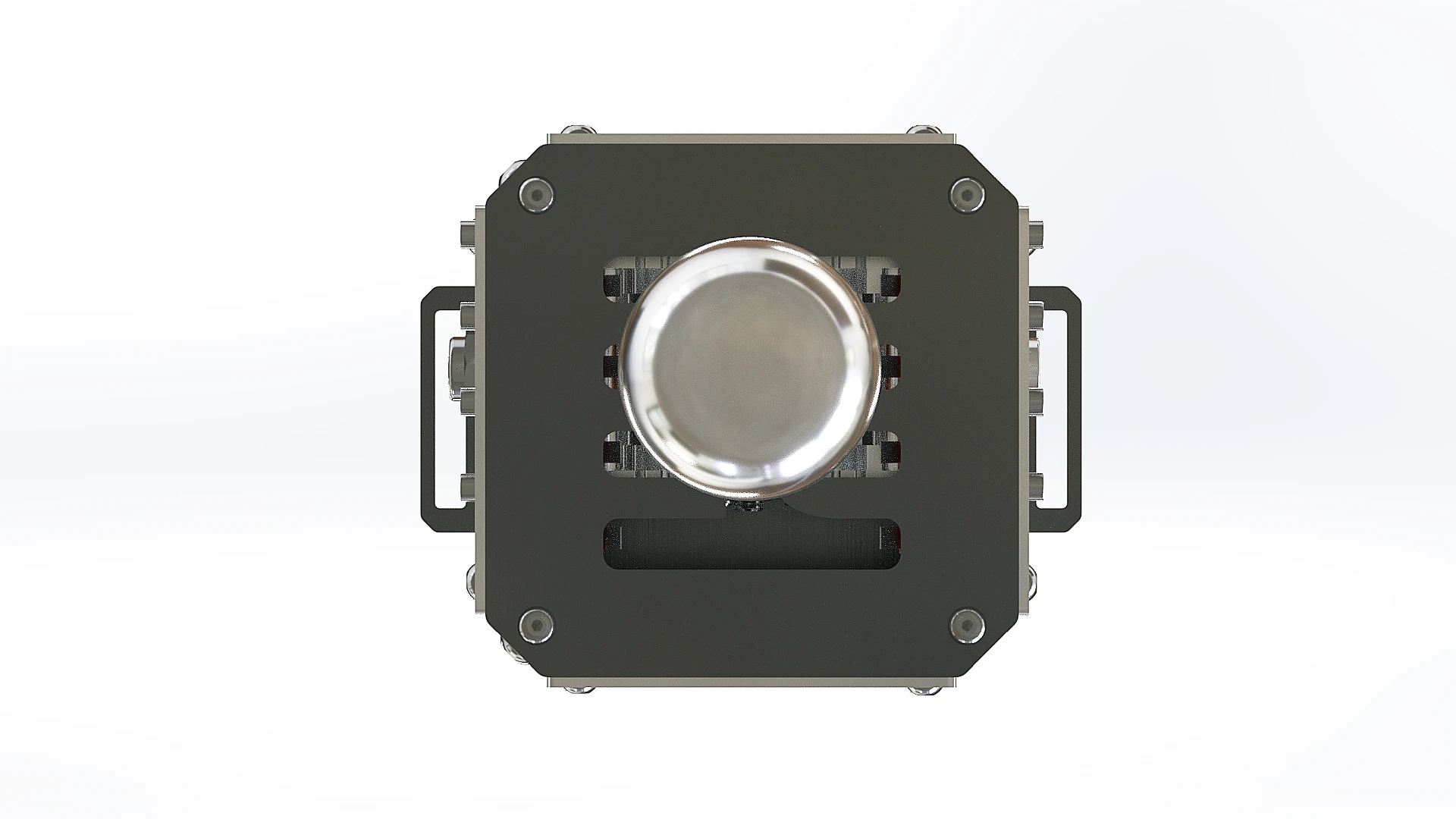
The H Shifter measures 132 mm in height (without the Knob). The width is 106 mm.

An image showing the dimensions is available directly on the product page.

  • Outer diameter: Ø19mm (required)
  • Inner diameter: Ø6mm (required)
  • Width: 6mm (required)

They can, of course, be found in the Bill of Materials.

To build a Shifter, you need to have all the parts in the “DXF Files” folder cut out. This does not include the
“Alternative DXF Files” folder; as the name suggests, these are alternative parts.

The quantity is indicated in the filename, but if no quantity is specified, it means a single piece is required.

There are three parts that require bending:

  • Ball Bearing Support – 2mm Thickness
  • Corner Fixing – 2mm Thickness – Quantity 4
  • Microswitches Support – 2mm Thickness – Quantity 8

You will find the bending guide in the “Folding Guide – A3 PDF Sheet” folder, and a STEP version for each
file.

The bends are very simple, involving only 90° or 45° angles.

Screws (Diameter x Length):

  • M3 x 6 – Quantity 14
  • M4 x 8 – Quantity 20
  • M4 Nuts – Quantity24
  • M4 x 10 Countersunk Bolt – Quantity 4
  • M6 x 12 – Quantity 8
  • M6 x 40 Threaded Round Spacers – Quantity 4
  • M5 x 12 – Quantity 4
  • M5 Nuts – Quantity 10
  • M5 x 16 – Quantity 6
  • M3 Nuts – Quantity 32
  • M3 x 10 – Quantity 16
  • M3 x 8 – Quantity 4
  • M8 x 170 No Head Screw – Quantity 1
  • M6 x 16 – Quantity 2
  • M6 Lock Nuts – Quantity 2
  • M5 Lock Nuts – Quantity 6
  • M8 x 115 (or M8 x 120) Half Thread Bolt – Quantity 1

Important note: for each nut, try to use the thinnest one possible.

  • 30mm Traction Spring (Quantity: 2)
  • 20x10x20mm Spring (Quantity: 1)
  • M8 Female Rod end SI8TK M8 Right (Quantity: 1)
  • 19x6x6 Bearing (Quantity: 2)
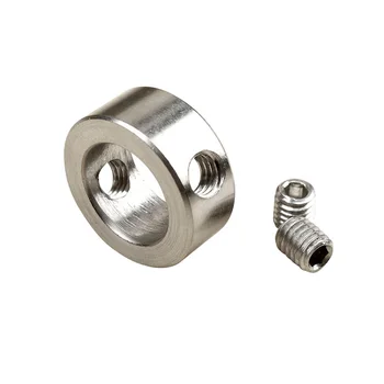
  • Ø8mm Drill Bit Stop Collar (Quantity: 1)

The list of required parts is in the Bill of Materials

Three thicknesses are used: 2 mm, 3 mm, and 5 mm.

The thickness of each part is indicated in the file name (3mm Thickness, 5mm Thickness, 2mm Thickness).

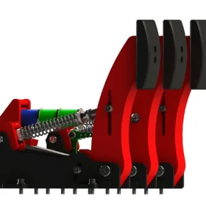
Simply slide the spring loops onto the M5 screws. You can see how it’s done in our tutorial on the 3D Printed H-Shifter: https://www.diysimstudio.com/2024/05/23/diy-h-shifter/#Building_Guide
Simply use the provided 3D-printable cable routing clips (STL files):

  • Microswitch Wire Management – ​​Quantity: 2
  • Thin Wire Management – ​​Quantity: 4

Route the microswitch wires through the clips and then connect them to the PCB (which should be mounted on the right, on the plate featuring the USB port).

You can watch the “10 – Wire Management” video for more details.

Reviews

There are no reviews yet

Add a review
You must be logged in to post a review Log In

Post here your issues or your questions, I will answer you as soon as possible.


People Also Bought