


")
")
")
")


Description
FEATURES
• EASY TO BUILD
This building kit has been designed to be easy to build without expensive tools or advanced knowledge! A complete tutorial is provided, the goal was to make its construction as accessible as possible to the general public. In the event of a issue, the customers will receive free assistance in the “Help & Questions” section.
• CHEAP
This pedal can be built with a small budget ranging from 100€ and 300€, depending on the parameters you have chosen (production choice, USB Boards…).
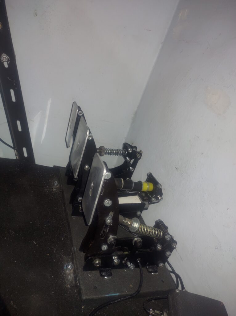
• STRONG
This Pedal has a very strong structure, stable and smooth mechanism.
• ADJUSTABLE
The Pedal has been designed to allow a maximum of adjustments! You can adjust angle, hardness, stop and positioning of each pedals according to your feeling.
• REALISTIC
This Pedal offers accurate realism, with a feeling adapted to each pedals (degressive clutch, soft and hard two-phase brake, linear accelerator).
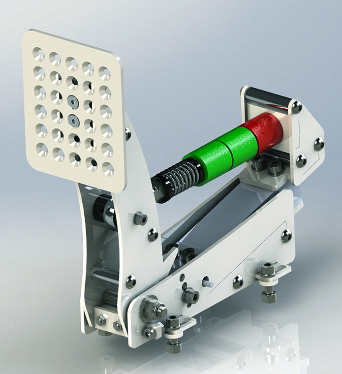
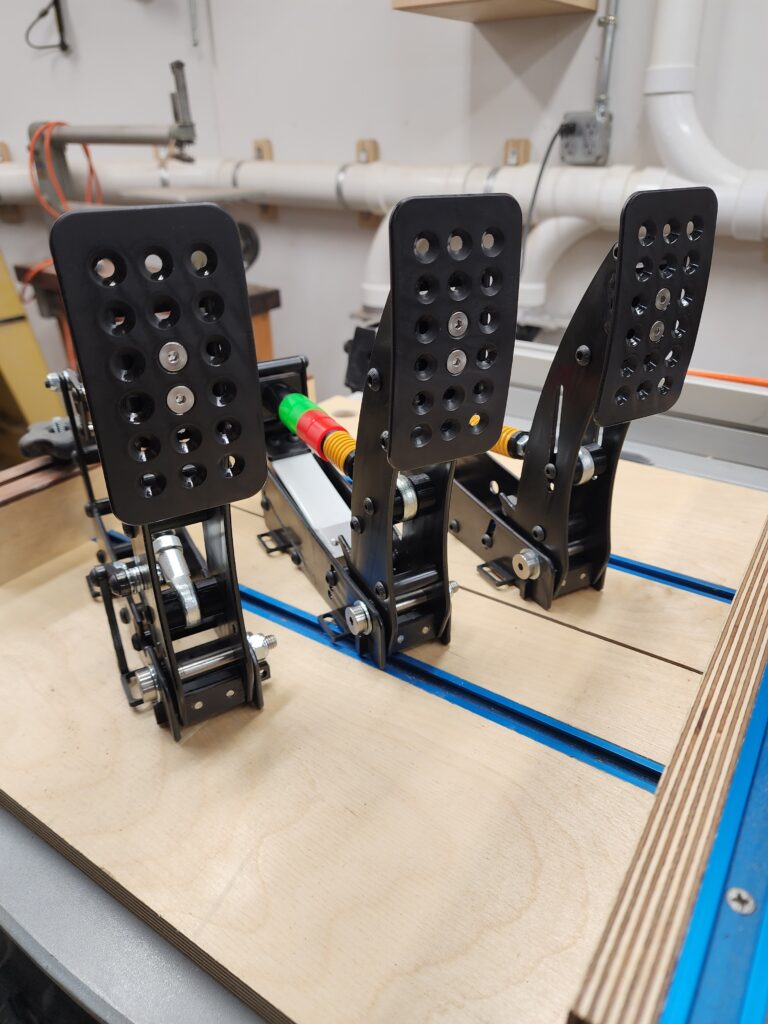
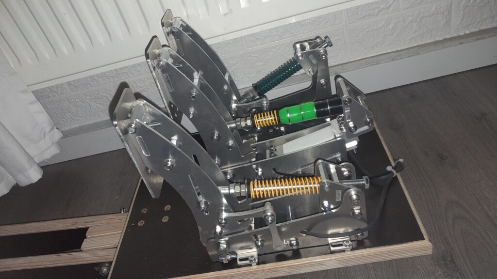
• HANDSOME
This is a very beautiful Pedal, with shapes inspired by those used in real cars, and a polished metal finish with mirror effect. The 3D Printed edition is just as pretty as the standard metallic version.
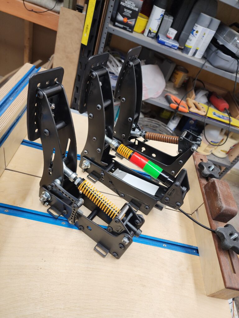
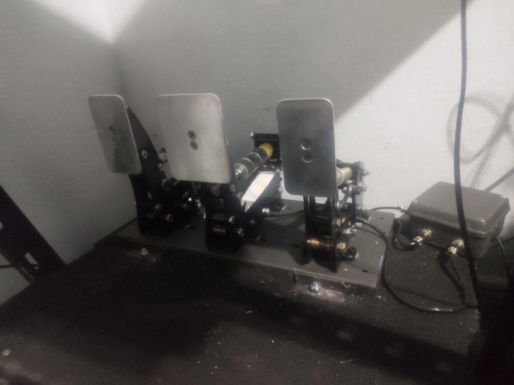
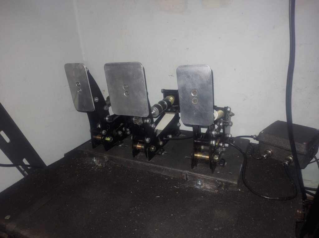
PEDAL SET
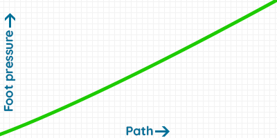
• THROTTLE
The throttle pedal is linear, you can adjust the hardness, angle, stop and the footrest position.
Concerning electronics, it’s a potentiometer fixed by two levers with a very solid structure.

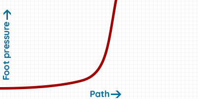
• BRAKE
The brake is made up of one spring and many elastomers which enables the two stages of braking: soft then hard. The feeling is adjusted by changing the combination of elastomers and / or by tightening the spring.
The pedal is designed to take more than 100kg of pressure!
Concerning electronics, it will be a 120kg pressure sensor.
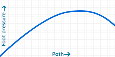
• CLUTCH
The clutch is almost similar to the throttle, but has a degressive mechanism allowing to simulate the clutch of a real car (only the 3D Printed Edition is linear).

REVIEW
IN-GAME TRIAL
PEDAL BUILDING
BUILDING OF THE 3D PRINTED EDITION
ADDITIONAL TUTORIALS
Parts buying guide: Springs and Elastomers
- Throttle Spring [Quantity 1] [Option: Length: 90mm, Diameter: 20mm]
- Throttle Spring alternative 1 [Quantity 1] [Option: length 90mm, Diameter 20mm]
- Throttle Spring alternative 2 [Quantity 1] [Option: Color: yellow, Specification: 18x9x100]
- Brake Spring [Quantity 1] [Option: Length 30mm, Diameter 20mm]
- Brake Spring alternative 1 [Quantity 1] [Option: Length 30mm, Diameter 20mm]
- Brake Spring alternative 2 [Quantity: 1] [Option: Color: yellow, Specification: 18x9x40]
- Clutch Spring [Quantity: 1] [Option: Color: Brown, Specification: 18x9x100]
- 3D Printed Edition Clutch Spring [Quantity 1] [Option: Length: 90mm, Diameter: 20mm]
- Bushing/Elastomers [Quantity: 2 minimum] [Option: 85A or/and 90A]
- Alternative link for Elastomers #1
- Alternative link for Elastomers #2 [Quantity: 3 minimum] [Option: D25/8,5x25mm]
- Alternative link for Elastomers #3
- Alternative link for Elastomers #4
- Alternative link for Elastomers #5
- Solution-elastomeres [Options: Length 250mm, External diameter Ø32mm, Internal diameter Ø8,5mm, Shore/Hardness 80-90-99]
Parts buying guide: Electronics
• POTENTIOMETERS AND LOADCELL
- P260 potentiometer [Quantity: 2]
- Potentiometers 2 [Quantity: 2] [Option : 10k Ohm] Note: you need M8 washer to fix this potentiometer
- Brake Loadcell [Quantity: 1] [Option : 120kg]
• USB BOARDS (only one of them is mandatory)
- Leobodnar BU0836-LC 12-bit [Quantity: 1]
- Leobodnar LC-USB 16-bit [Quantity: 1]
- USB Type A to B for Leobodnar and DSD boards [Quantity: 1]
- DSD 12 Bit Controller [Quantity: 1] [Option: 12 Bit Controller with AMP]
- DiyMore Arduino Leonardo board [Quantity: 1] Note: only with HX711 Loadcell Amplifier
- Micro USB cable for DiyMore Arduino Leonardo board [Quantity: 1] [Option: 3m]
- Arduino Pro Micro [Quantity: 1] [Option: Mini USB 3-6V] Note: only with HX711 Loadcell Amplifier
- Mini USB cable for Arduino Pro Micro board
- HX711 Loadcell Amplifier [Quantity: 1] [Option: HX711] How to Convert Your HX-711 Board From 10Hz to 80Hz
- Sparkfun HX711 Loadcell Amplifier [Quantity: 1]
• WIRING
- Shielded cable for Potentiometers [Quantity: 1] [Option: 3 cores 5 meters]
- 28AWG Cable recommanded for Arduino Pro Micro [Quantity: 1] [Option: 28AWG (3Cores) – 5 meters]
- Dupont wire cable 1 [Quantity: 1] [Option: 30cm, 3P]
- Dupont wire cable 2 [Quantity: 1] [Option: 40cm male to female]
- Weatherproof Heat Tube [Quantity: 1]
- Aviation Circular Connector GX12 [Quantity: 3] [Option: 3P for Throttle and Clutch, 4P for Brake]
- Metal Cable Gland M12 [Quantity: 3] [Option: M12X1.5 For 4-8mm]
• ALTERNATIVE CASES FOR THE USB BOARD
Parts buying guide: Tools
• MACHINING
- High quality flute Mill Cutter for Countersunk hole [Quantity: 1] [Option: 90°, one 1 Flute, 20.5mm] Note: for aluminium Foot plate
- Midrange flute Mill Cutter for Countersunk hole [Quantity: 1] Note: for aluminium Foot plate
- Metric thread Tap and Die [Quantity: 1] [Option: 12pc]
- 2.5mm Cobalt Drill Bit for the M3 potentiometer thread[Quantity: 1] [Option: 2.5mm]
- Pipe Cutter for Elastomer cutting [Option: 0-32mm, Scissors]
- PLA Filament 1.75mm
• SANDING AND POLISHING
- Electric sander
- 125mm sanding discs
- Coton polishing wheel [Quantity: 1] [Option: Cylindrical 60mm]
- FFP2 Face mask
- Metal polish
- Polishing bar
- Plastic brush for cleaning (after polishing)
- Paint brush
• ASSEMBLY
- 3 Hex Wrench Spanner [Quantity: 1] [Option: 3-4-5mm, 4-5-6mm]
- Allen Hex key [Quantity: 1] [Option: flat head]
- Alternative Allen Hex key
- Screw driver hand tool
- LED Flash light
• SOLDERING
- Electric soldering iron
- Soldering station 1
- Soldering station 2
- Soldering wire
- Soldering dross
- Soldering tweezers
- Wire cable stripper
- Metal soldering holder
- Plastic soldering holder
Required Screws
Screws for Lasercutting-Handcutting-CNC [PDF]
Screws for 3D Printed Version [PDF]
Aliexpress screws:
- Pandametal Screws Store : most of what you need is here
- Self-Lubricating Bearing for the Axis (optional) [Quantity: 3]
- Axis Shoulder Bolt [Quantity: 3] [Option: D10x8, 50mm]
- Noise absorber for the Pedal stop [Quantity: 1] [Option: Black or Blue or Red 10mm]
- M5x30 spacers for the Female rodend and the Throttle/Clutch Spring support [Quantity: 4] [Option : M5x30]
- M6x30 and M6x40 spacers for Fixed and Mobile parts [Option: M6x30, M6x40]
- M8 Female Rod end [Quantity: 3] [Option: SI8TK M8 Right]
- Flat head Screws
- M8x150 and M8x170 Semi-threated screws
- M8x150 and M8x170 Semi-threated screws (alternative link)
- M8 Washer Super Large for the Brake Elastomers [Option: M8(10PCS)316]
Parts compatibility
You can use others parts to build this pedal (apart from those listed in the required parts section), but you will need to check that they are compatible.
• POTENTIOMETERS
Ohm : 10k is recommanded, but 100k can also work (it depends at the USB Board)
Thread : between Ø6mm and Ø9mm
Shaft diameter : not to exceed Ø7mm
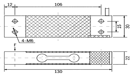
• LOADCELL
Weight : not below 100kg.
Loadcell dimensions:
• ELASTOMERS
Ø Inside diameter: min. 8mm, max. 10mm
Ø Outside diameter: not to exceed 35mm.
• SPRINGS
ØInside diameter: not below 8.5mm
ØOutside diameter: not to exceed 28mm
If you use springs with different dimensions, I advise you to create the spring centralizer part. You will need to download Freecad (it’s a free software) and read the tutorial that is provided. Everything is in the Alternative spring centralizer folder.
• ALTERNATIVE FOOTREST :
Material of the pedal
• LASERCUTTING
I recommend stainless steel.
For the few parts that need to be machined, I recommend aluminum because it is softer.
The parts that require machining are the following:
– Countersunks holes for the Footrests
– 2 holes to drill and tap for the potentiometer levers
All these machining operations can be avoided if you use 3D printing alternatives.
• 3D PRINTING
I recommand PLA or ABS, the filling will vary according to the pieces, and it will be indicated in the name of the files. Here are recommendations for printing 3D solid parts: https://3dpros.com/guides/optimizing-part-strengt
• HAND CUTTING AND CNC MACHINING
I recommend aluminum because it is a soft metal that is easy to work with.
How to get the required materials
• LASERCUTTING
I advise you to use the 3mm and 5mm “All-in-One” DXF files and request a quote from lasercutting companies near your home. All parts are flat, there are none to bend. So you can compare prices and choose the most profitable. On average, the asking price for cutting a stainless steel pedal is between 100€ and 150€ including VAT and shipping. You can save money if you make a combined order.
For France and Europe, I recommend the company ALPM, they provide a very good quality cut for a reasonable price.
• 3D PRINTING
You can buy a 3d printer, or find a 3d printing service like treatstock. Don’t forget the infill percentage if you want a strong product (especially for the brake pedal). The longest part that need to be printed is 220mm.
• HANDCUTTING
You need only sheets of papers, printer and Aluminium plates !
• CNC MACHINING
I recommand CNC Machining only if you own a CNC Rooter, otherwise it is not economically profitable enough compared to lasercutting.
• SCREWS
Bolt depot, Motedis and FixnVis.
Tolerances
Lasercutting DXF files and CNC Machining files : 0.2mm
3D Printing : 0.6mm


Very impressed with these! Thank you so much for putting together all the documentation and files. I was only able to get 7ga steel here in the states so I adjusted the slots for the difference in size. The pedals went together and installed/calibrated with no problems, after a very speedy response on an issue that ended up being my fault. I used plain carbon steel and then used a black oxide finish with a acrylic finish to protect it. The only thing I “added” or “upgraded” was the spacer for arms that connect the potentiometer, I couldn’t get the joints tight enough that they wouldn’t have any slop but still move freely without sticking. I ended up getting some small M6 thrust bearings off amazon for a few bucks. Now I can tighten the joints snug, and they still are silky smooth. Also make sure to lube the brake M8 bolt where it goes through the elastomer bushings, this pretty much stopped any squeaking from that, and if the throttle or clutch springs squeak, try rotating them a bit to find where they don’t. Worked for me.
Again thank you very much, looking forward to building the handbrake!!
very nice, happy with the pedals. genius Plans, Thank You for your work!
The pedals design is amazing, they look great. And they work as they look. Keep up the good work
Les plans sont au top, je dirai qu’il manque juste a intégré la liste des matériaux (meme si présente sur le site)